Thursday, November 7, 2024

Bino Body Mount - build a travel mount for binocular astronomy

Using the Bino Body Mount while reclining
I recently took a dark sky vacation to Arizona. I wanted to bring my 15x70 Garrett Optical binoculars, but they are 5.5 lbs., and I can't hand hold that with any kind of steadiness. I had previously built a zero gravity chair mount, but I wouldn't have access to a zero gravity chair. 

I was pondering compact and, of course, inexpensive solutions, and came upon this post on Stargazers Lounge. The observer uses a mini-tripod with one leg removed, resting the other two legs on his shoulders. This seemed like a great idea, except you still have to keep your elbows raised, which introduces both unsteadiness and fatigue. 

The Bino Body Mount
Taking that idea a step further, I devised a very simple apparatus that I call the Bino Body Mount, which solves the problem of having to raise your arms by adding a 90 degree handle to each side of a basic wood frame. You don't have to buy a mini-tripod, just a cheap 1x2 furring strip (my go-to wood for this kind of thing), a binocular tripod adapter, a 1" 1/4-20 stud knob, two star knobs, two hanger bolts, a flat washer, two fender washers, two neoprene washers, four wood screws, and two tennis balls (well, three really because they come in 3-packs). See parts and tools list at the end.

The mount breaks down flat for packing by removing three knobs. It's very lightweight, and can be used standing or sitting in any type of chair. Your arms stay at your side to provide comfortable support when standing and rest on the arms of your chair when sitting. As you recline further back toward the zenith, the shoulder bars transfer more and more of the weight to your shoulders, resolving the problem of raising your arms and tiring quickly. The Bino Body Mount also improves the view and fatigue factor with any size binoculars because you don't have to hold them in front of your face with your arms raised. 

Using the Bino Body Mount while standing

For Comet C2023/A3 (Tsuchinshan-ATLAS), I sometimes used the mount standing because it was relatively low to the horizon and I really didn't need a chair. It worked great. I wouldn't recommend standing and looking anywhere near the zenith with binoculars, whether handheld, on a Bino Body Mount, or on a tripod. That's just painful and awkward.


Using the Bino Body Mount while sitting

For objects near the horizon, you can sit up and rest your arms on the chair arms. 

Note: That's a Bino Bandit around the eyepieces. It's a neoprene eyepiece light shield that I highly recommend despite it's relatively high cost because it works so well. 


You're not going to get rock steady views with this, but surprisingly close, and your arms and neck won't get tired. My brother and I spent many hours on our Arizona vacation using these, and they worked great with almost no fatigue. You will primarily see a jiggle from your heartbeat. You can look around anywhere in the sky that you could just handholding the binoculars. You can loosen the knobs to tilt the bino bar at whatever angle works best for you. You can adjust focus with one or both hands.

At this point, I am using the Bino Body Mount for all of my binocular astronomy observations, regardless of whether I'm traveling or not. It's simple, it's lightweight, it's compact, it's inexpensive, it's easy to build, and it works very well.


Build it

Thread-to-eye measurement
The critical measurement is the distance from the tripod threads in between the barrels of your binoculars to the end of the eyecups, what I call the "thread-to-eye" measurement. The correct distance places the binocular eyepieces exactly where they would be if you were handholding them. This doesn't need to be super precise- within 1/2 or 1/4" is fine. You can tilt the bino bar when observing to make up for any slight error.

If you have multiple binoculars with different thread-to-eye distances, as is the case with my Meade roof prism binoculars, you just drill a pair of holes in the shoulder bars at the correct distances and you can easily reposition the bino bar as needed. Or you could just make two mounts!

See the parts and tools list at bottom of the post.

Step 1:
Measure and cut

Measure and cut a 1x2 furring strip into five pieces. You can make them whatever lengths that work for you, but I made the two shoulder bars 12" long, which accomodates most porro prism binoculars with an approximately 4" thread-to-eye distance. On a second Bino Body Mount, I cut the bars 13-1/2" long for my Meade roof prisms, since the measurement is about 6" for them. The bino bar (the crosspiece that holds the binoculars) is 11". The two handles are 12". One six or eight foot furring strip will be plenty and leaves some extra in case of "constructor error."

Step 2:
Bino bar

The bino bar
Drill a roughly 11/64" hole in the center of both ends of the bino bar (the 11" piece) and insert a 2" 1/4-20 hanger bolt into each, using the "two-nut" technique (thread two nuts on the end, tighten them together, then screw in by turning the upper nut, screw out by turning the lower nut). The threaded end of the hanger bolt should stick out far enough to accomodate the 5/8" width of a furring strip, another 1/8" for a neoprene washer, 1/16" for a flat washer, leaving about 1/4" for the knob to screw onto. So leave about one screw thread of the wood screw part showing and you should be fine. You can always adjust it.

Drill a 1/4" hole in the middle of the bino bar. This will hold the tripod adapter using the 1" stud knob and flat washer.

Step 3:
Shoulder bars

Various parts labeled
Drill a 1/4" hole in each shoulder bar where the bino bar crosspiece hanger bolts will be inserted. This should be the measurement above plus about 6 inches. So for a 4" thread-to-eye measurement, drill the hole about 10" from the end of the shoulder bar that will rest on your shoulder. Put a neoprene washer between the bino bar and the shoulder bar, then on the outside of the shoulder bar, a 1/4" flat or fender washer and the knob.  

Step 4:

Test the fit. People's bodies vary, so if the above calculation doesn't work, make an adjustment by drilling a hole a little closer or further from the end. This is the important part, so make sure you get it right and it's comfortable for you. Adding tennis balls will give you a little more distance, and putting a thicker pillow behind your head or wearing a hood will give you a little less. It doesn't have to be perfect, just close enough to work for you. 

Remember you can make minor adjustments by loosening the side knobs and changing the bino bar tilt slightly. I like to have the binoculars tilting slightly downward compared to the shoulder bars (see images above), except when observing near the zenith. In that case, I like to have the binoculars pretty much pointing straight out parallel with the shoulder bars, especially when observing in a chair that doesn't recline very far.

Cut an X or hole in two tennis balls and stick them on the ends of the shoulder bars so they fit snugly and won't fall off easily. This is harder than it sounds. Tennis balls are tough! I used a large folding knife to poke an initial hole, then cut the rest until it fit snugly on the end of the 1x2. See this video, or if  you have an electric carving knife, this video. I always wear heavy leather gloves when working with sharp things near my hands that could slip. 

Step 5:
Handle bars

Attach the handle bars on the outside of the shoulder bars about 7" from the ends that rest on your shoulders with two wood screws per side. You can also add tennis balls to the handle bars for the ultimate in opulence.

Step 5:
Finishing touches

With fender washers under the two side knobs, a flat washer under the bino mount knob, and neoprene washers on each end of the bino bar (to help keep it from slipping without having to overtighten the knobs), test it all and if no further adjustments are needed, sand and paint the wood pieces. 

Completed Bino Body Mount with 15x70s mounted


The final assembled Bino Body Mount (with my 15x70s mounted).


Front view of Bino Body Mount


Front view showing placement of the neoprene washers.


The Bino Body Mount disassembled

The pieces disassembled for packing in a suitcase. This mount has longer shoulder bars with two sets of holes to accomodate both my porro and roof prism binoculars. No tools required to assemble and disassemble. Just unscrew three knobs.


Two Bino Body Mounts!
What's better than one Bino Body Mount? Two Bino Body Mounts! One for me and one for my brother. I hope you enjoy yours!


[1/27/2025 update] Some tips on use:

  • Always carry the apparatus by holding the binoculars. That way, if you forgot to tighten something or it got loose, it's the mount that will hit something, not your binoculars.
  • Apropos the above, periodically check that the three knobs are tight.
  • Some tilting of the binoculars from side to side on the tripod adapter is desirable so that if you are looking off to the side a bit it will stay lined up better with your eyes. 
  • When observing near the horizon while sitting, I like to rest my palms on the side knobs with my fingers curled around the ends of the handle bars, tucking my elbows in for support

Parts list

1x2 furring strip (6 ft.)

Binocular tripod adapter (example)

1" 1/4-20 stud knob (most come in multi-packs- good for lots of projects)

Two 1/4-20 2" diameter threaded five-star knobs

Two 1/4-20 2" hanger bolts

Three 1/4" hole flat washers 

two 1/4" neoprene washers

Four 1-1/4" wood screws

Two tennis balls


Tools:

Tape measure or ruler

Power drill with 1/4" and 11/64" (or close) drill bits, and phillips head bit (or screwdriver, or both)

Hand or power saw

Two 1/4" hex nuts and two 7/16" combination wrenches or pliers (to screw in the hanger bolts)

Sturdy pointed knife to make holes/cuts in tennis balls

Sandpaper, tack cloth, paint, and paintbrush

Nice to have but not essential: 

    Mitre box (to make straight cuts)

    Clamps (to hold the wood for sawing and drilling)

Saturday, October 26, 2024

Upgrading from starter eyepieces

Svbony SV135 7-21mm zoom eyepiece
Beginner telescopes come with very basic eyepieces to get you started as soon as you open the box. Sometimes these are pretty decent and will work for you for a long time and sometimes they suck, but most people want to upgrade at some point. Unfortunately, many people now tend to upgrade too much, too soon.

My recommendation is to get an inexpensive zoom eyepiece to go with your new telescope. There are quite a few under $100 that are available. Even though I have a nice Baader Hyperion 8-24x zoom, this year I purchased a Svbony SV135 7-21mm zoom. It's a lot lighter, about six times cheaper, and a decent performer, getting mostly good reviews on Cloudy Nights for its price, and I agree. I got one for my brother, too, and he loves it. [Note: If you wear glasses or want a slightly wider view, you might want to go with the Svbony SV191 7.2-21.6mm zoom, which is a bit more expensive and not quite as sharp.]

Svbony SV135 zoom eyepiece showing the Moon at different focal lengths
With a zoom, you will get a feel for how different objects in the sky look in various eyepiece focal lengths, which determine the power, and what works best in your telescope. (Telescope focal length ÷ eyepiece focal length = power. For example, a telescope with a 750mm focal length with a 10mm eyepiece in it will give you 75x.) If you do eventually upgrade your eyepieces, after you get to know the sky better and know what you like to look at, you can keep the zoom and use it when you want to travel light, for quick sessions, planetary and lunar detail, double stars, and for outreach. That's what I do.
Zoom eyepieces like the SV135 have a narrower field of view than many comparably priced eyepieces and generally aren't quite as sharp or well corrected for aberrations, although this one does tolerably well. By twisting the barrel, you are able to zoom into exactly the desired power, replacing a large set of eyepieces with just one. 

As you progress, you might want wider or sharper views, which come at a cost. Televue eyepieces, the premier example of consistently high end eyepieces, are expensive because they give you well-corrected wide views, which don't come cheap. But a relatively cheap zoom allows you to experiment with different powers on different objects so you can find what works best in your telescope for you. Then you have a better idea of what you want if you decide to upgrade. This also allows you to take full advantage of your new telescope immediately. 

Screenshot from the Sky Safari Pro app.
Well, maybe not immediately. More critical than upgrading eyepieces is learning the sky and how to find things in it with your telescope. See the Space Walk Among the Stars sound guides, which will help you find some wonderful deep space objects, as well as posts on determining directions in your telescope, how to set up your telescope for starhopping, the Astrohopper app, and others. 

The internet is full of observing guides. I would start by visiting the Sky & Telescope site, with their Interactive Sky Chart and lots of information for beginners. You'll find tons of information there. Also visit Cloudy Nights, the premier amateur astronomy forum. The Beginners Forum will keep you occupied for many cloudy nights to come and provide a place to ask questions.

Left: Screenshot from Sky Safari Pro. Apps like this help you locate objects in the night sky and can even control your telescope if it is go-to equipped.

Saturday, October 19, 2024

Add an azimuth circle to a your Dobsonian and ditch that straight-through finder

Close up of pointer on azimuth circle
A couple of years ago I added azimuth circles to the bases of my two Dobsonian telescopes, and recently added one to a go-to tabletop dob to replace the often unreliable go-to system. Coupled with a digital angle gauge, available in hardware stores or online for about $20-30, this allows me to dial in the altitude and azimuth coordinates for any object, creating a "push-to" system. I can literally find anything anywhere now without straining to look through a straight-through finder, as long as I can see it in my scope and it's included in my sky charting app. 

The main advantages are:

  • No neck strain looking through a straight-through finderscope or red-dot finder (this was the impetus for me)
  • Ability to find objects in areas of sky without a lot of bright stars for starhopping, or in light pollution
  • Quick and easily repeatable
  • No finicky and power-hungry electronics (the angle gauge takes two AA batteries that last a long time)
  • Inexpensive


What you need and how you use it


Screenshot from Sky Safari Pro 6
You will need an app to look up the alt-az coordinates for an object in real time. As the earth rotates, these coordinates constantly change, and are based on your location and time. As always, I recommend Sky Safari Pro (Android or iOS) as a great all-round app that will list the coordinates and show you the star field once you've gotten close to an object. Even the Basic version has the alt-az coordinates, but for a smaller database of objects.

In the Sky Safari Pro screenshot at left, I have selected galaxy NGC 7331, centered it, and the current azimuth (88.5) and altitude (62.4) are shown in the upper left. Make sure you center the object. If you don't, it will not show the correct alt-az coordinates. Then move your scope tube so the pointer on your azimuth circle is set on 88.5 and your digital angle gauge shows 62.4. Look in the eyepiece and, if you have properly leveled and aligned the scope, the object should be in there somewhere. If not, check the wider view in the RACI finderscope if you have one, find the object, and adjust the pointer as needed.


The following are the steps required to find an object with the azimuth circle/angle gauge method. Steps 1-6 are done at the beginning of each observing session. Step 7 is repeated for each object you want to observe.
  1. Set the telescope base so that the azimuth circle is roughly aligned with either the Sun or Moon during daylight, or any bright object at night.
  2. Level the scope. A cheap bubble level will do fine. I use an app. I made some plywood squares with tread tape on them for rough leveling and use composite shims for fine tuning.
  3. Put in a low power eyepiece and find a bright object that's easy to align on without a finderscope. Just sight along the tube at something not too high in the sky. Once centered in the eyepiece, adjust your RACI finderscope, if you have one, to match.
  4. Look up the alt-az coordinates of the object in Sky Safari or your preferred app. The altitude should match your digital angle gauge plus or minus the accuracy of the gauge. Make sure your gauge is sitting evenly on the top of the scope tube.
  5. Adjust the azimuth pointer to match the azimuth shown in the app. Don't wait too long, as this will be constantly changing.
  6. Look in the eyepiece and you should see the object, or at least the star field around or near the object. Identify the exact location within the field by comparing your view with the star chart.
  7. To move to another object, look up the new object's coordinates and move the scope until they show on the gauge and circle. You may have to adjust the azimuth pointer slightly for inherent inaccuracies if you are in a different part of the sky, but you will be close.
I added right angle correct image (RACI) finderscopes to my scopes to verify I dialed the coordinates in correctly, help identify dim objects among star patterns, or move around an area to look for other nearby objects. You can get by with just having one RACI finderscope and putting a shoe on each telescope, then moving the finderscope between scopes. I do that with a 6x30 finder for my 4.5 inch and 6 inch scopes. I prefer an 8x50 for my 10 inch, and it can handle the extra weight of the bigger finderscope better.

Get a digital angle gauge


This is the easy part. If you have a telescope with a metal tube, pretty much any digital angle gauge will have a magnetic base that will work well with it. If you don't have a metal tube, you can stick on a metal plate or design some other system to attach the angle gauge. You'll need to cover the display with transparent red tape or something to dim it down to acceptable levels.

Digital angle gauge with cover
I chose a Klein Digital Angle Gauge because it has white numbers on a black background, so minimal light, and all I needed to do was cover it with a tranparent red material. I used the plastic pack that the gauge came in as a holder for the red material, and duct taped in a scrap piece of red acrylic I had leftover from resizing a laptop shield and some craft foam. It slips over the gauge with a friction fit. Just make sure the red material doesn't blur the display making it unreadable. The Wixey is another popular digital angle gauge. You can try to find one without a backlight if you are just going to use a red flashlight to look at it.

Making and installing an azimuth circle


There are many variations on the azimuth circle because telescopes are different and observers are different. Check out the megathread Degree Circles on Cloudy Nights for ideas and pictures. The standard way is to make the azimuth pointer movable, usually using magnets. You can also make the circle movable, but that's usually more complicated. You decide how you want to do it, but here's what I did.

Azimuth circle installed on 10-inch
For my 10 inch, I cut a notch in the round bottom of the rocker box and glued a paper azimuth circle to the round ground board beneath that. The azimuth pointer rides on a magnetic strip in the notch so I can adjust it during initial alignment and make subsequent fine adjustments.


Azimuth circle installed on 4.5-inch
For my 4.5 inch, my design of the base did not lend itself to simply gluing on a paper circle and cutting a notch, so I cut a circle out of a 1/8" thick sheet of FPVC, which is a light, semi-flexible vinyl, using a craft knife. I made the cut slowly and wore leather gloves for protection. I had to go over the cut mark multiple times until it cut all the way through. Then I glued a printed paper azimuth circle to the FPVC circle and assembled it below the bearing material disk. I drilled a hole in the center through which the bearing bolt passes. Here's my post on Cloudy Nights about my 4.5 inch project, with additional pictures.


Azimuth circle installed on 6-inch
For the 6 inch, I couldn't separate the round bottom of the rocker box from the triangular ground board for fear of messing up the electronics, so I cut the FPVC into a ring shape, glued on the paper azimuth circle, then sliced the ring in two places and attached it to the ground board with some double sided foam tape.


Close up of azimuth circle showing cuts to fit it to the telescope base
The cuts are next to 55 degrees and 295 degrees so I could attach the ends of the pieces to the "ears" of the ground board that you can see sticking out slightly from below the azimuth circle. I used small pieces of double-sided foam tape. You only need to make two cuts, 120 degrees apart, so you can position the bigger ring piece and then the smaller one to complete the circle.


New table for tabletop telescope
The azimuth circle added 3/4" to the radius all the way around the base. I had to make a new, larger table for the scope because the circle now blocked the eyepiece holders. This new one is 20" in diameter. The original was 18". I took the opportunity to eliminate the unused 2" holes that I had on the old one and make four 1.25" holes on each side, so no matter where I am sitting, I have lots of places to store eyepieces. I also used 3/4" plywood. White paint makes it easy to see where you're putting stuff and makes it less likely someone will walk into it in the dark. See my post on making a table for a tabletop telescope .

Use the website blocklayer.com to design and print an azimuth circle that fits your telescope. Some people take it to a FedEx or another store that will print it for you. I tried that and they printed it slightly oversized, so I just printed it in several pages on my home printer and fit them together. That introduces a tiny bit of inaccuracy, but you're likely not going to get it perfect anyway. It'll still work fine.

The Blocklayer site has a huge number of templates of all types, and it's fun to browse. But for this project, I used Circle Divider templates. There is a green "Metric Version" indicator at the top, which is actually a button to change it to Metric from the default "Inch Version." Leave it showing Metric.

Due to the popularity of creating azimuth circles for telescopes, Blocklayer has added a template for this specifically: Protractor - Setting Circle. It does essentially the same thing as the Circle Divider template, and you could use that instead. It appears they have removed the option to set the scale counterclockwise, which you would need if you had a movable circle and a fixed pointer.

Screenshot from Blocklayer.com
You have many options, including having the numbers on the inside or outside of the scale, black-on-white or white-on-black, size and length of tick marks, numbering of every 10 or every 5 degrees, etc. Choose what you like, but think about readability from where you are observing and using a red light to see it. Change the "Diameter inches" setting to what will work for your scope, then hit "Calculate" or use the slider. The circle needs to fit on your lower ground board or fabricated circle or ring.


These are the settings I prefer:
  • Black print on white background
  • Tick lines (default)
  • Primary increments 10 degrees (default)
  • Number orientation = Radial -90 (so you can read the numbers correctly at the eyepiece)
  • Outer marks - note that if you choose Outer marks, the diameter you chose becomes the inner diameter, so you need to adjust the size so the outer diameter is the diameter you need (e.g., your ground board is 22 inches, and so you need a 22 inch outer diameter circle, or a tiny bit smaller). Font size, tick thickness, etc. will affect this, so check the info in the center of the circle on the Blocklayer page and adjust everything with the sliders until you have it the way you want it and your outer diameter is the correct size.

If you like my suggested settings and have the same scope, you can download the azimuth circle PDF that I used for my Sky Watcher Virtuoso GTi 150P here. If you need a 22 inch outer diameter azimuth circle, here is the one I created for my 10-inch Hardin Deep Space Hunter. The Cloudy Nights Degree Circle megathread has a bunch of other files created for different scopes.

Once you have the circle the way you want it in Blocklayer, select "diagrams to PDF" at the top, and in the page that comes up, select the paper size you will be printing on, put in the file name, and hit the "Trim" button. Full printing instructions are at the bottom of the Blocklayer page. Hit the "PDF 1" button in the lower right below the circle (to exclude printing the tape that otherwise would also print out). 

PDF print preview showing the azimuth circle printed over several pages
Your own computer's settings will determine how you print it once downloaded, but make sure you are printing at 100% and select "tile large pages" or a similar setting that will print the circle over several pages. If you have it commercially printed, make sure they print at 100%. If it doesn't come out right, just adjust in Blocklayer and try again. I like to print a little smaller than the diameter of the ground board so the edge doesn't peel up.

Once printed, check the fit against your FPVC circle or ring. If it's good, glue it carefully onto the circle or ring using contact cement, making sure you get complete coverage with no bubbles or bare spots. Then spray the paper with several coats of a fixative (I use Aleene's Acrylic Sealer - Matte Finish) outdoors because these often have really bad fumes, especially Aleene's. 

Once dry, mount the circle or ring between the ground board and the lower rocker box. For my 4.5 inch, I drilled a 1/4 inch hole to fit the 1/4-20 center bolt, and the circle sits underneath the azimuth bearing plate. Yours might be different. For the Sky Watcher Virtuoso GTi 150P (6 inch), I had to make two cuts to remove an arc 1/3 of the circumference because I couldn't separate the ground board and rocker box. I then reassembled it into a ring and attached it to the ground board with a few small pieces of double sided foam tape. I tried larger pieces of foam tape, but fitting them under the rocker box board was a mess because they would stick before I could get the pieces in position. Smaller foam tape pieces worked much better and it still holds well.

You'll need to make an azimuth pointer. I made mine from a scrap of thin aluminum flashing material I had from a roof job, but you can pretty much use anything. I attached a tiny rare earth magnet to it using duct tape. I couldn't find any glue that would hold permanently- duct tape to the rescue again! Then I took a piece of magnetic tape and attached that to the rocker box board, so that the pointer will move with the rocker box. The azimuth circle is fixed on the ground board and the pointer rotates with the scope. 

For the Sky Watcher Virtuoso GTi 150P, I switched to using a strip of Velcro instead of magnets, because I kept knocking the pointer when reaching for the azimuth bearing lock knob. You can use anything as long as the pointer can be moved over an arc of about 30 degrees. Any less and it will be harder to rough align the scope when you first set it down and still be able to put the pointer within range. Put the pointer where you'll see it easily from your normal observing position. 


Telescope with digital angle gauge and azimuth circle
The Sky Watcher Virtuoso GTi 150P with new azimuth circle and larger table. The digital angle gauge sits on the top front of the metal lower half of the tube.

Saturday, October 12, 2024

3D Moon flyover

Full Moon with 3D label
I'm a big 3D fan, especially of stereogram pairs that require no special equipment to see. 

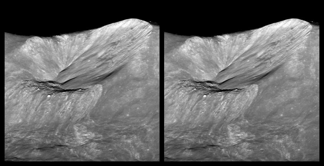
Here is a variety of images featuring different formations on the Moon in 3D. Seeing these from a new perspective adds to our understanding of what we observe in our telescopes. In this case, we are seeing them closer than we ever could from Earth, at differing angles, and in simulated 3D. 

These are stereoscopic pairs using the parallel viewing method. See the instructions for my 3D constellations for details on how to view these. With practice, almost everyone can learn to do it. It's worth the effort!

These images were taken by the Lunar Reconnaissance Orbiter Camera, which has been orbiting the Moon on the LRO since 2009. It has taken some spectacular images of the lunar surface, a few of which are reproduced here in 3D. All images are courtesy NASA/GSFC/Arizona State University. I created the 3D versions using Owl3D and created the location maps with Virtual Moon Atlas. Definitely check out the links to details of the images and browse the other incredible images on the LROC web site. If you have those cardboard anaglyph glasses, they have quite a few images in anaglyph 3D, although the 3D depth tends to be unrealistically exaggerated in some cases.

Many of these features can be observed with small backyard telescopes. The Moon's phase is critical, because features at or near the terminator, the line between night and day, are highlighted with long shadows and can be seen easier. Features near the limb, such as the crater Stevinus, can also be seen better when the Moon's wobble, or libration, presents it a little more favorably towards us. A steady atmosphere and a telescope adjusted to the ambient temperature is also very important. Of course, if a feature is on the far side, we won't be seeing it from Earth. 

Check out this cool NASA simulation to see how much the Moon varies in phase and libration throughout a year. You can also check out how the Moon will look now or at another time for the remainder of this year using NASA's visualization tool.


Unnamed crater between Lowell W and Mare Orientale

This 2.8 mile wide crater sits at the edge of the crater Lowell W and Mare Orientale on the Moon's far side. This was taken when the LRO was at an altitude of 47 miles, facing west. Not visible from Earth. See details about this image.

Stereoscopic pair of Unnamed crater between Lowell W and Mare Orientale


Location of the unnamed crater near Mare Orientale
Mare Orientale on the lunar far side. The arrow just below crater Lowell W points to the unnamed crater in the image above.


Aristarchus central peak

Aristarchus is visible in small telescopes, binoculars, and even with the unaided eye. It is often one of the brightest features visible because it is a young crater, 450 million years old, that hasn't had time for its ejecta material to darken. Here is a closeup crop of the central peak of the crater, taken by LROC from an altitude of 60 miles, facing west. The central peak is about 1,300 feet tall and 9,800 feet wide. The crater is over 2 miles deep. The best time to view Aristarchus is four days after First Quarter or three days after Last Quarter, but try for it around Full Moon and you'll see how bright it appears. See details about this image. 

Stereoscopic pair of Aristarchus central peak


Aristarchus is 25 miles in diameter. Here's another view. See details about this image.

Stereoscopic pair of Aristarchus


Location of Aristarchus
Location of crater Aristarchus in Oceanus Procellarum. South is up.


Messier crater

About 8.7 miles across, Messier is located in Mare Fecunditatis and may have been formed by a low angle impact, causing it's oblong shape. With an apparent size of nearly 7 arcseconds, Messier and its companion crater, Messier A, as well as the two small rays pointing east from Messier A, can be seen in small telescopes. The best time to view Messier is four days after New Moon or three days after Full Moon. See details about this image.

Stereoscopic pair of Messier crater


Location of Messier crater
Location of Messier crater in Mare Fecunditatis. South is up.


Komarov crater floor (detail)

Located on the far side of the Moon, the floor of 53-mile-wide Komarov crater is covered with deep fractures created when magma rose from the mantle more than 2.6 billion years ago. The largest fractures are about 1,600 feet deep and 8,000 feet wide. Not visible from Earth. See details about this image.


Stereoscopic pair of floor of Komarov crater


Location of Komarov crater

Lunar Orbiter image of Mare Moscoviense with Komarov crater in the left foreground.


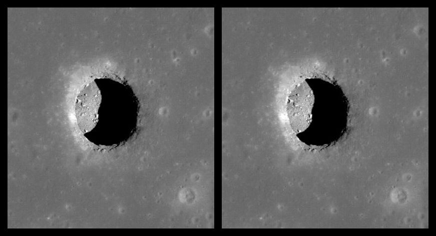
Mare Tranquillitatis pit

Pits are relatively small features that may have formed due to the collapse above a lava tube. They were first discovered in 2009 and over 200 have now been identified. The sharp edge of the opening of this pit is about 330 feet across, and the depth is estimated to be about the same. Computer modeling suggests the temperature in the shaded part of the pit may be relatively stable at about 63 degrees F, and there may be a more extensive cave or cave network. The pit is too small to be seen in backyard telescopes. See this article for details.

Stereoscopic pair of Mare Tranquillitatis pit


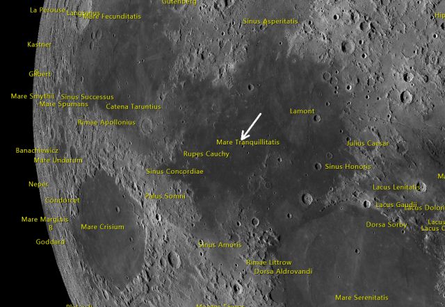
Location of Mare Tranquillitatis pit
Mare Tranquillitatis pit location. South is up.


Mound in Stevinus crater


A fractured mound inside Stevinus crater. This may have resulted from squeeze-up of molten rock in the impact that formed the crater. The mound is about 2 miles wide. Stevinus can be seen in small telescopes, although our view is at an angle, Stevinus being near the Moon's southwestern limb. The central peak can be spotted. The mound is only about 1.6 arcseconds in diameter and may just barely be detected in some amateur images. The best time to observe Stevinus is three days after New Moon or two days after Full Moon, with a favorable libration. See details about this image.

Stereoscopic pair of Stevinus mound


Location of Stevinus crater
Location of Stevinus crater. South is up.


Location of Stevinus dome
Location of the dome within Stevinus crater. North is up.


Wallach crater

Wallach is located in Mare Tranquillitatis. The asteroid or comet that hit the basaltic surface stirred up brighter material from underneath. Wallach is about three miles in diameter. This image was taken from an altitude of about 58 miles. A small telescope with good seeing can pick it out from the mostly flat floor of the mare using higher powers. The best time to observe Wallach is five days after New Moon or four days after Full Moon. See details about this image.


Stereoscopic pair of Wallach crater


Location of Wallach crater
Wallach's location in Mare Tranquillitatis. South is up.


Hell Q crater


One of the many satellite craters (smaller craters near a named crater) named after Hungarian astronomer Maximilian Hell, Hell Q is a very young crater only about 2 miles in diameter. At only 1.8 arcseconds in apparent size, Hell Q requires a 6-inch or larger scope with higher power. The best time to observe it is one day after First Quarter or Last Quarter. See details about this image.


Stereoscopic pair of Hell Q crater


Location of Hell Q crater
Hell Q location. The crater Tycho is just above  center on the right, near the Terminator. South is up.


Tycho

The 53-mile-wide crater Tycho has a large and prominent ray system. This oblique image was taken from an altitude of about 37 miles. The west wall on the far side in the image is more than 14,000 feet high. Tycho is an easy target in any telescope, best observed one day after First Quarter or Last Quarter. The bright rays are most prominent around Full Moon, however. See details about this image.

Stereoscopic pair of Tycho crater


The central peak of Tycho. The image is about 3/4 of a mile wide. The boulder on top is about 100 yards wide. See details about this image.

Stereoscopic pair of central peak of Tycho crater


Lichtenberg B

Lichtenberg B is a young three-mile-wide crater located in Oceanus Procellarum. The ejecta darkens over time, so the presence of bright ejecta is an indicator that the crater is relatively young. Lichtenberg B can be spotted with small telescopes. Being very close to the northeastern limb, it is best observed six days after First Quarter or five days after Last Quarter using higher powers. See details about this image.

Stereoscopic pair of Lichtenberg B crater


Location of Lichtenberg B crater
Lichtenberg B location in Oceanus Procellarum


Earth over Compton Crater

Taken at 83 miles altitude, the Earth appears over the far side crater Compton. See details about this image.

Stereoscopic pair of Earth over Compton crater


Thursday, September 19, 2024

New Binocular Space Walk audio guide - Clusters in Cassiopeia and Perseus

I've added a new Binocular Space Walk audio guide, "Cruising for Clusters in Cassiopeia and Perseus." The guided tour takes you through the northern constellations Cassiopeia and Perseus to find 16 of the brightest open clusters in that part of the sky, as viewed from mid-latitudes in the northern hemisphere. It lasts about half an hour, but provides many opportunities to pause the recording to admire the objects and take breaks. Here's the link to the page, which is also available under Quick Hops on the right. Enjoy!

Binocular Space Walk - Cruising for Clusters in Cassiopeia and Perseus